Why Factory Acceptance Testing is the Smart Move

[February 2011] Even in this age of solid state products, ordering a transmitter is a major deal. Beyond the need to get the performance and footprint required, as well as the right price, Rolin Lintag shows the process of acquiring a transmitter should include another major aspect.
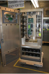
Before the transmitter ever gets to your site, before it is even boxed, there is something important you must do: go to the factory and participate in the Factory Acceptance Testing. If I am to describe the relationship of the engineer to a transmitter he just bought, it is like setting up an eyeball meeting before taking his mail-order bride home.
Yes, it is an additional investment for the transportation and perhaps a night at a hotel. But compared to the cost of a large transmitter, it is a minor add-on. Compared to the price of the smaller transmitters, it is still cheap if it saves you just one night of troubleshooting.
Why FAT is Cool
Factory Acceptance Testing (FAT) is a must for the following reasons:
1. It gives you the confidence that the transmitter you are getting works as expected prior to being shipped out to the site.
2. You get together on a personal basis with the factory engineers who can show you exactly how the transmitter works and answer all questions that may need to be answered in the field.
3. You get to observe and know how the transmitter behaves so that when you get it on the air and find it is doing otherwise, you will know it was due to shipping and not due to factory defect.
These are the justifications I used in order to get FAT trips approved by employers. Conducting a FAT is a proactive way of protecting such a huge company investment.
Preparing For the FAT
Before you leave the office, there one very important something you need to have in hand – a detailed checklist. To paraphrase a certain advertisement, “never go out without your checklist.”
To prepare that checklist, start by studying the claims of the transmitter manufacturer that made you buy it in the first place. Jot down those claims, so when you get to the factory floor you can ask them to prove them to you on your specific transmitter.
 It is worth noting that even transmitters of the same model have their own individual physical and electronic peculiarities, so as you do your checkout of the transmitter, do the best you can to ensure those your transmitter has are acceptable to you.
It does not hurt to start by checking to see if all the modules are in the right places, firmly seated, and the screws and bolts are tight – with the appropriate washers in place
And, while this might seem like a lack of faith in the factory, it is really just being careful. A simple typo on the original order sheet could present you with a transmitter tuned to a different frequency than your license states. Taking care of that at the factory will save lots of pain and agony later.
Specifications
At top of your list should be the important specifications like total power output (TPO) and the overall AC to RF efficiency.
Find out how the manufacturer tests the TPO and with what particular instrument set-up they use so that you can do something similar on site for FCC compliance. Verify the value of the directional couplers being used and the level of confidence on the reading (directivity of the coupler).
You should also make sure that the front panel metering of the transmitter is tracking the power measurements. When the TPO meter shows 100% it should correspond to your licensed TPO. If not, find out how to calibrate the meter.
Relative to the TPO is the system AC to RF efficiency. You need this to get a good grip on the actual power consumption and heat load so you can verify AC and HVAC requirements. This is also the time to hear the normal sounds of the cooling system.

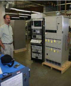
Stuart Peters tests a transmitter at the Broadcast Electronics plant
Another parameter that you may want to see for yourself is the output spectrum of the transmitter. Have it printed out so that you have a reference when the proof is done after the site installation. Make it easy, have a USB drive with you to save an MPEG image of the spectrum for future reference.
There are other important specifications that you may want to ask for, depending on whether it is FM or AM and if digital or analog. (Signal Quality is no longer a big issue since all manufacturers can satisfy that requirement; I do not waste my time on them.)
System Diagnostics
My other main concern was to ensure the protective circuitries are working correctly. You do not want to find out that the overload circuits are not working only after you actually needed them during on-air operation!
During some past installations, I have discovered the overload circuits had not been tested during the assembly – and problems cropped up while on-air. One experience I remember on a new high power HF transmitter is that the toroid used for over-current protection on the B+ did not trip the breaker on a current overload condition during a PM test. After coordinating with the manufacturer, they sent us another toroid to replace the one in service. Imagine what could have happened if an actual current overload occurred!
It is much better for the manufacturer to demonstrate to you that the RF output overload protection, for example, is working on your transmitter. If there is an automatic power cutback, have that demonstrated, too. The reason for this approach is so you can have full confidence that the overload protections are working like they should.
Any discrepancy can and should be corrected right there at the factory, saving you from a lot of frustration and coordination back and forth later on.
Operating With Failed Parts
For multiple modules, try pulling out one and see how the transmitter responds to a “failed” amplifier.
A recent experience with one transmitter was that a whole bank of four power amp modules died when I pulled out only one. This dropped the TPO to 32% – which is tantamount to being off the air and definitely non-compliant with the FCC.
Fortunately, I discovered this during a FAT and the manufacturer was able to trace the problem to a loose connection on a combiner load. You can imagine what problems that loose connector could have caused after going through shipping and installation, and I would have been saddled with this problem if it showed up during on-air operations.
Connecting to the World
One of my concerns when a transmitter arrives on site is how to hook it up to my station’s remote monitoring and control system. Just where exactly is that terminal block? What interlocks need to be in place before power will come up?
We all know how many employers will want that transmitter on-line as soon as possible when they see it delivered to the site. However you simply cannot expect the technical manual to give you quick answers when you are in a hurry to get a transmitter on-the-air. On the other hand, the time you save by figuring things out in the factory instead of on the site can make the difference between turning the equipment on-air on time – or getting delayed due to a lack of correct information.
Finding out right at the factory how to connect my monitoring system to the transmitter has saved me from a lot of pain. You even can plan for the wiring and even custom label the transmitter connections while still at the factory.
Networking – The Old Way – Still Works
Most important of all – and yet something often forgotten – is getting to know the factory engineers face-to-face. Then, you can connect a face to the voice on the phone should you need to call them later on.
I also find it helpful to know which factory engineer designed and/or constructed a particular section of the transmitter about which I need information. Reinforced by my experiences over the years, I prefer to go straight to the most reliable source of information.
Remember that even though there may not be a perfect transmitter, there is such a thing as a very supportive manufacturer. Service is what sets the champion manufacturer apart from the mediocre. –
– –
Romualdo “Rolin” Lintag, CSTE, is Chief RF Engineer for Victory Television Network in Arkansas. His email address is: rolin_lintag@yahoo.com
